Installing Speed Sensors on the Trawl
You can install the sensor on the headrope or grid, depending on its functions.
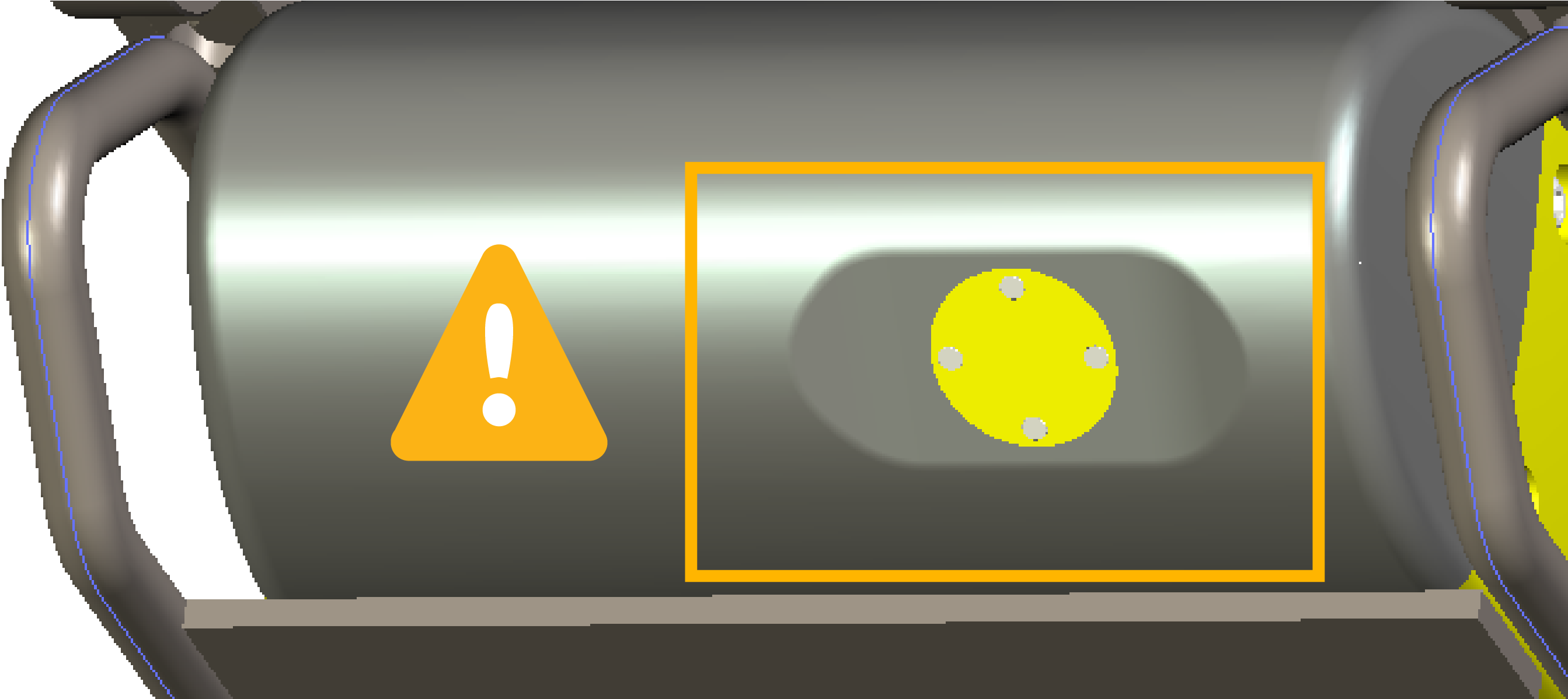
Handling precaution and a good maintenance of the EM log head is essential for the proper operation and lifetime of the flow sensors. Make sure to always use a protective cage when using the sensor. The protective cage must be approved by Marport. Any additional protective devices installed in front of the head may disrupt the flow and therefore alter the water speed measurements.
Even when the sensor is protected with a cage, make sure the head of the sensor does not hit any rail or protruding object when hauling the trawl on deck.
Headrope
The Trawl Speed, Symmetry and Speed Explorer sensors can be installed on the headrope to monitor the movements of the trawl.
The sensor must be placed below the headrope, EM log pins facing down, in order to send signals to the correct direction. The sensor must be placed in a way that there is less than +/- 5 degrees of pitch and roll. You may need to add floats to the back of the sensor to achieve this.
When the Speed Explorer is installed on the headrope, you may not see the footrope. If you want to see it, move back the sensor of a few meters.
The sensor is maintained in the cage by a latch mechanism. Pull the cord at the back of the sensor to release the latch and remove the sensor from the cage. The cage will stay mounted to the headrope.
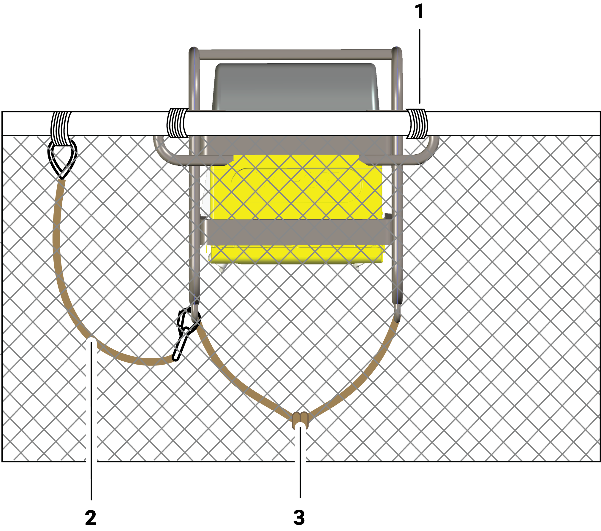 |
1. Cage attached to the
headrope 2. Safety wire with small shackles on both ends to secure the sensor 3. Rope passing between 2 housing attachment lugs and attached to the net |
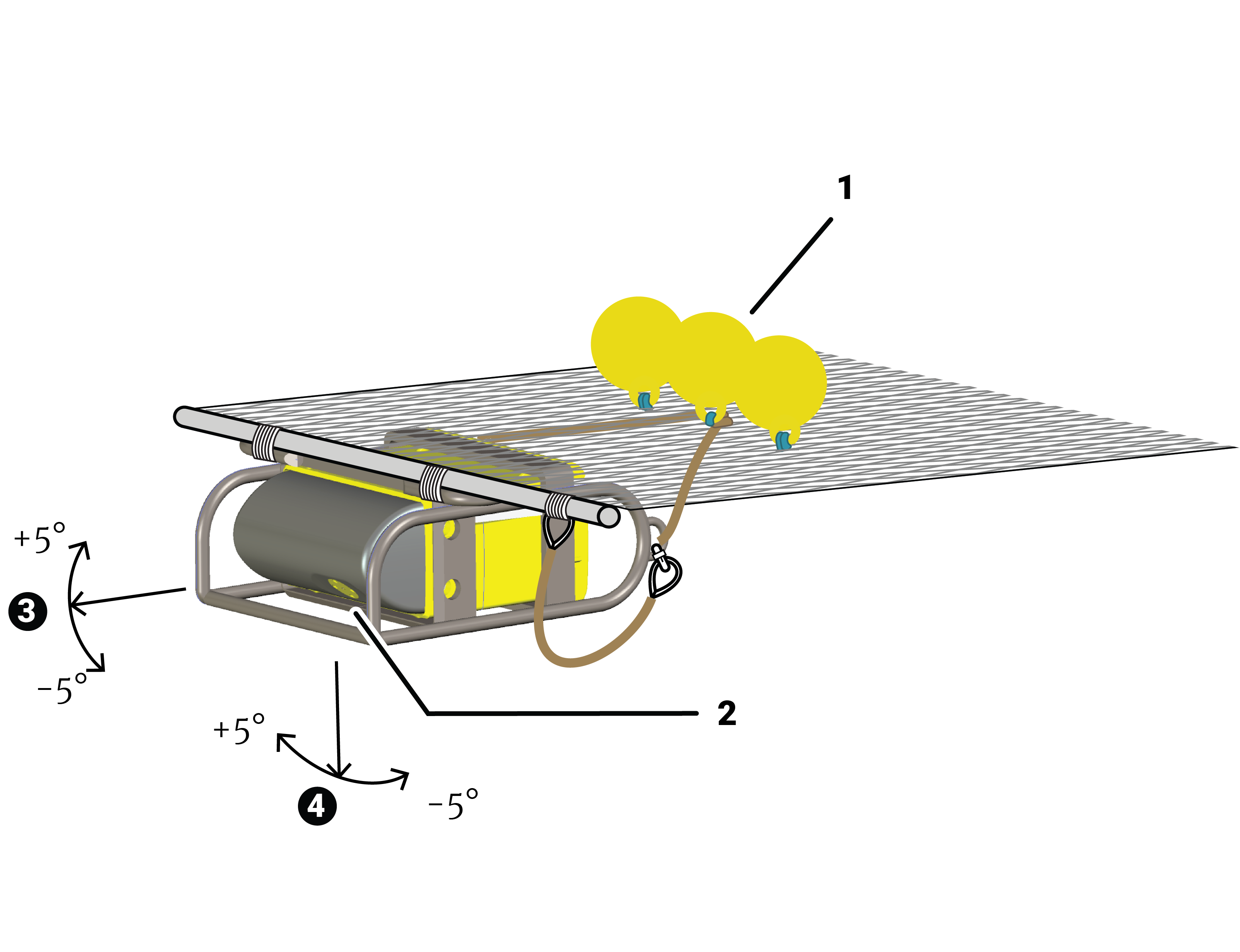 |
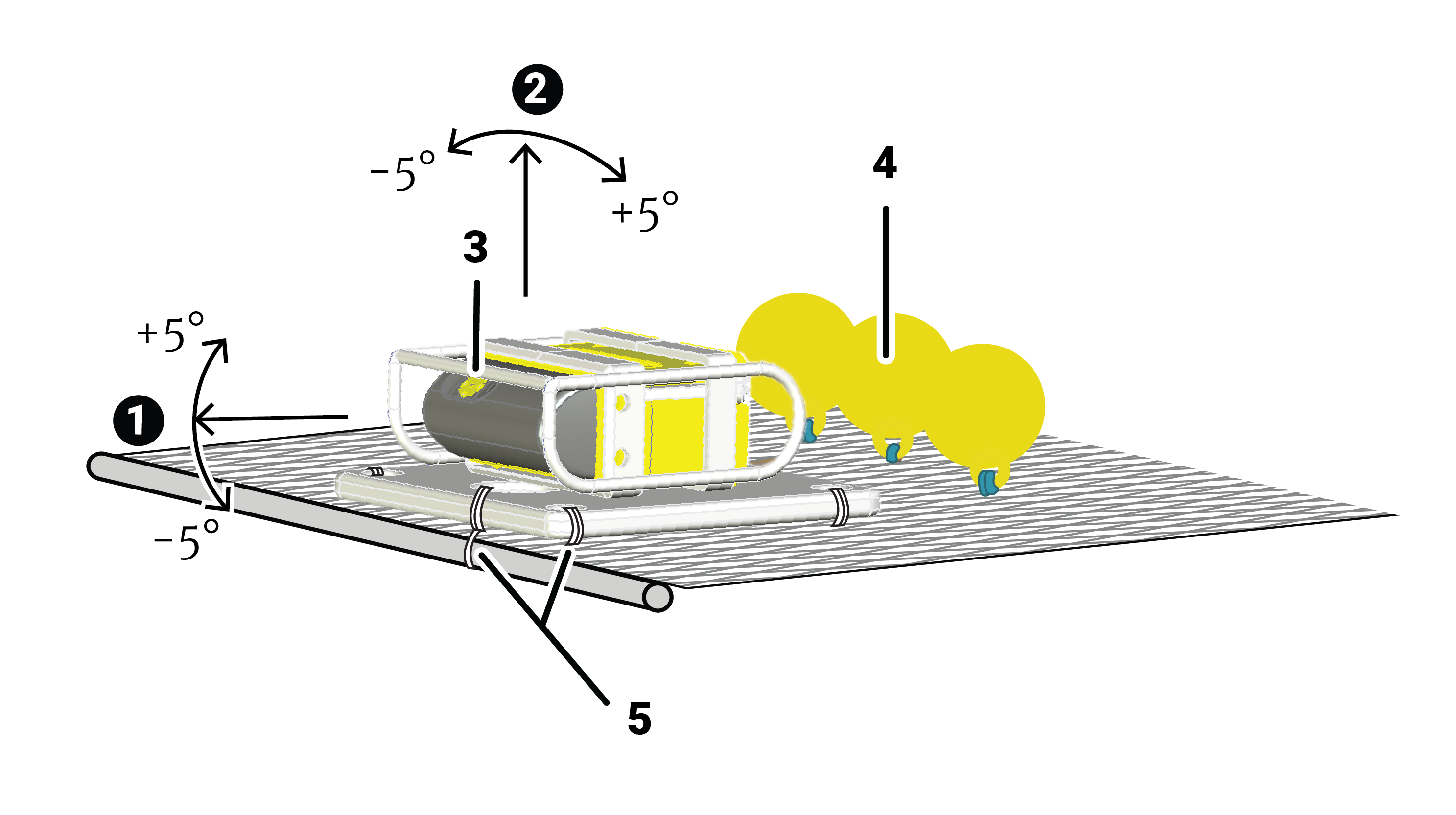
1. Floats at the back help stabilizing
the pitch and roll of the sensor. 2. EM log pins facing down. Make sure nothing is in front (rope, floats): it would impede its signal. 3. Maximum pitch + 5° / - 5° 4. Maximum roll + 5° / - 5° |
The Speed Explorer can also be installed upside down, with the EM log pins facing up instead of down. In this case, the Speed Explorer is installed on a board to provide more stability. The aim of this installation is to prevent the EM log pins and transducer to hit the deck when the trawl is hauled.
A specific configuration needs to be applied to the Speed Explorer to correctly work in this setup. Contact your local dealer or Marport office for instructions.
 |
1. Maximum pitch + 5° / - 5° 2. Maximum roll + 5° / - 5° 3. EM log pins facing up. Make sure nothing is in front (rope, floats): it would impede its signal. 4. Floats at the back help stabilizing the pitch and roll of the sensor. 5. Ropes attaching the board to the headline and net. |
Grid
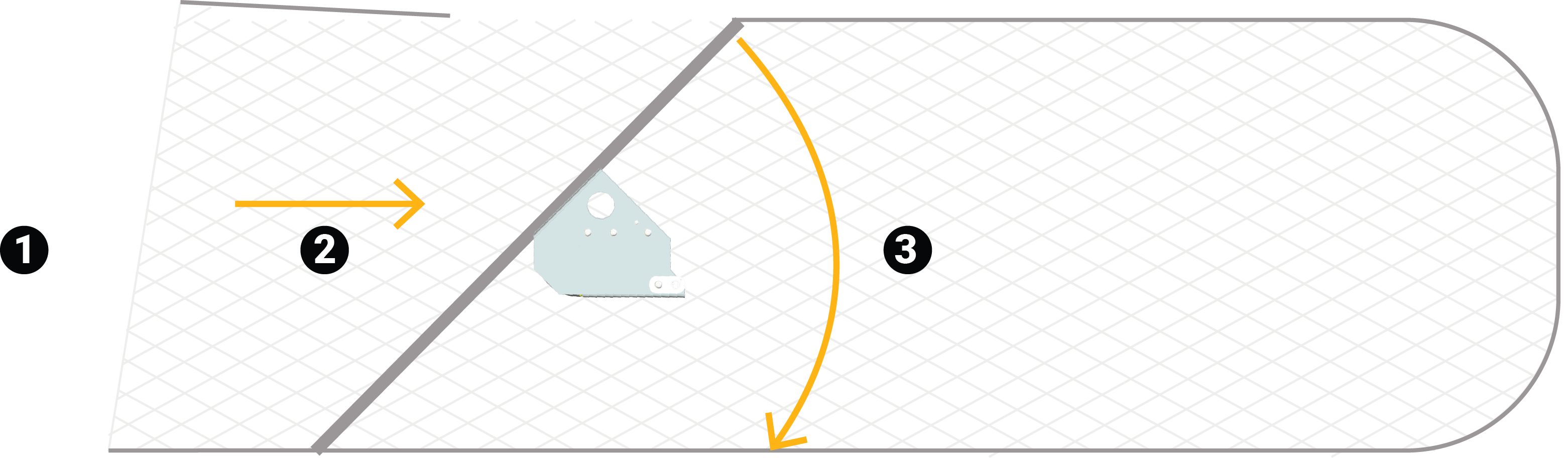
1. Vessel / 2. Direction of the flow / 3. Angle of the grid = 45°
 |
| 1. Attached to the grid with a stainless steel plate and fastenings / 2. Grid angle = 45° / 3. Grid sensor must be parallel to the seabed / 4. Safety wire between the sensor and the cage to secure the sensor |
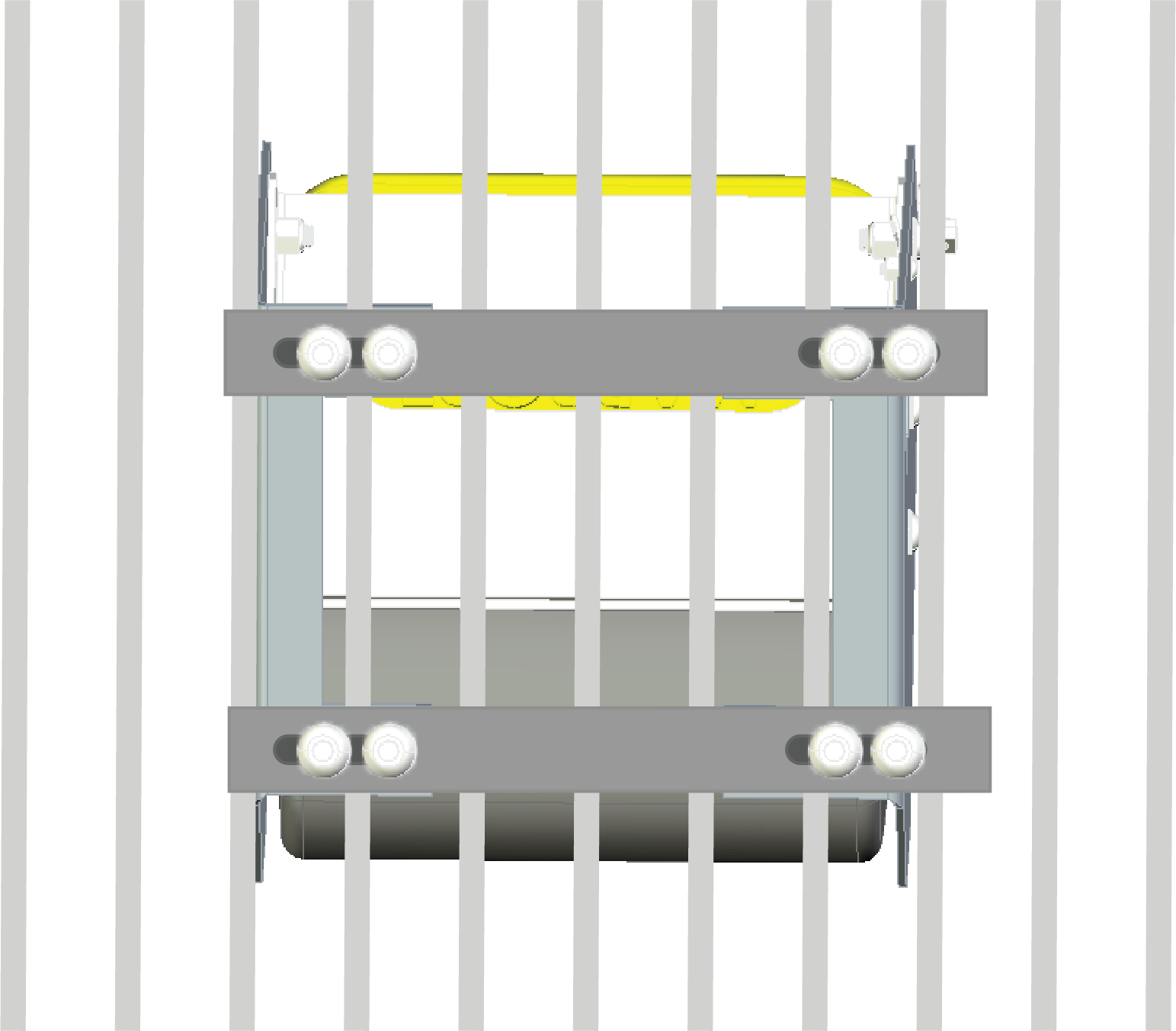
The sensor is attached to the grid with stainless steel plate and fastenings (not supplied by Marport), like on the image below: