Configuring the Hydrophones
You need to configure the hydrophones to correctly receive signals from the sensors.
Before you begin
Important: The two receiving hydrophones must have a minimum
distance of 1 meter between each other.
Important: You need to remove the 50kHz notch filter on the wideband preamplifiers.
Important: On M4 and M6
systems, the receiving hydrophones must be both connected to a hydrophone input
between H1, H2 and H3 or both between H4, H5 and H6. The transmitting hydrophone for a Slant Range must be connected to a
different set of hydrophone inputs than the receiving hydrophones (for example, if the
receiving hydrophones are connected to H1 and H2, the transmitting hydrophone must be
connected to a hydrophone input between H4, H5 and H6).
Tip: To help you remembering the configuration, always begin to configure
the port hydrophone, then the starboard hydrophone. This way, most of the values
associated with port side will be smaller than those of the starboard side
(hydrophone number, node numbers...).
Procedure
-
From Scala2, click Menu
 > Expert Mode
and enter the password copernic.
> Expert Mode
and enter the password copernic.
- Right-click the IP address of the receiver at the bottom of the page, then click Configure Receiver.
- From the left side of the page, click Hydrophones.
-
Add the two receiving hydrophones, then enter the
following settings:
-
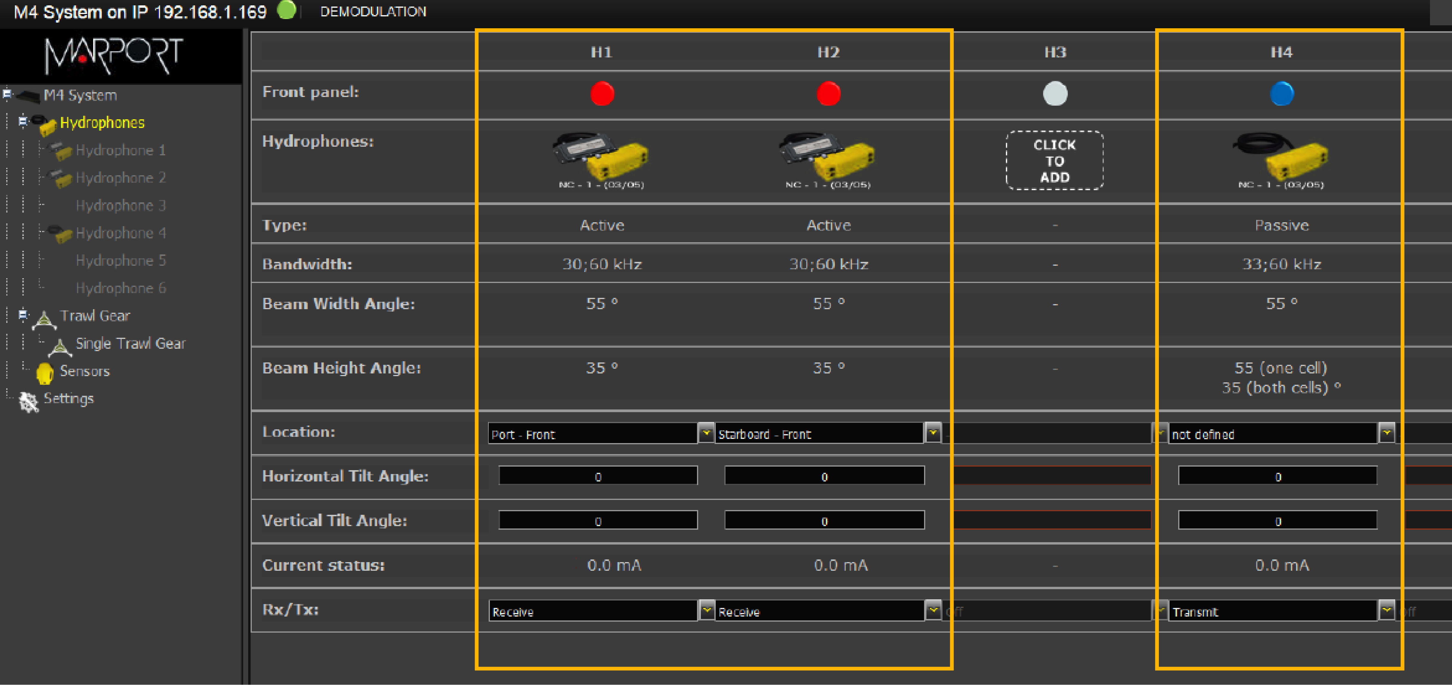
If you have Slant Range sensors:
Figure 1. Hydrophone configuration for Spread sensors 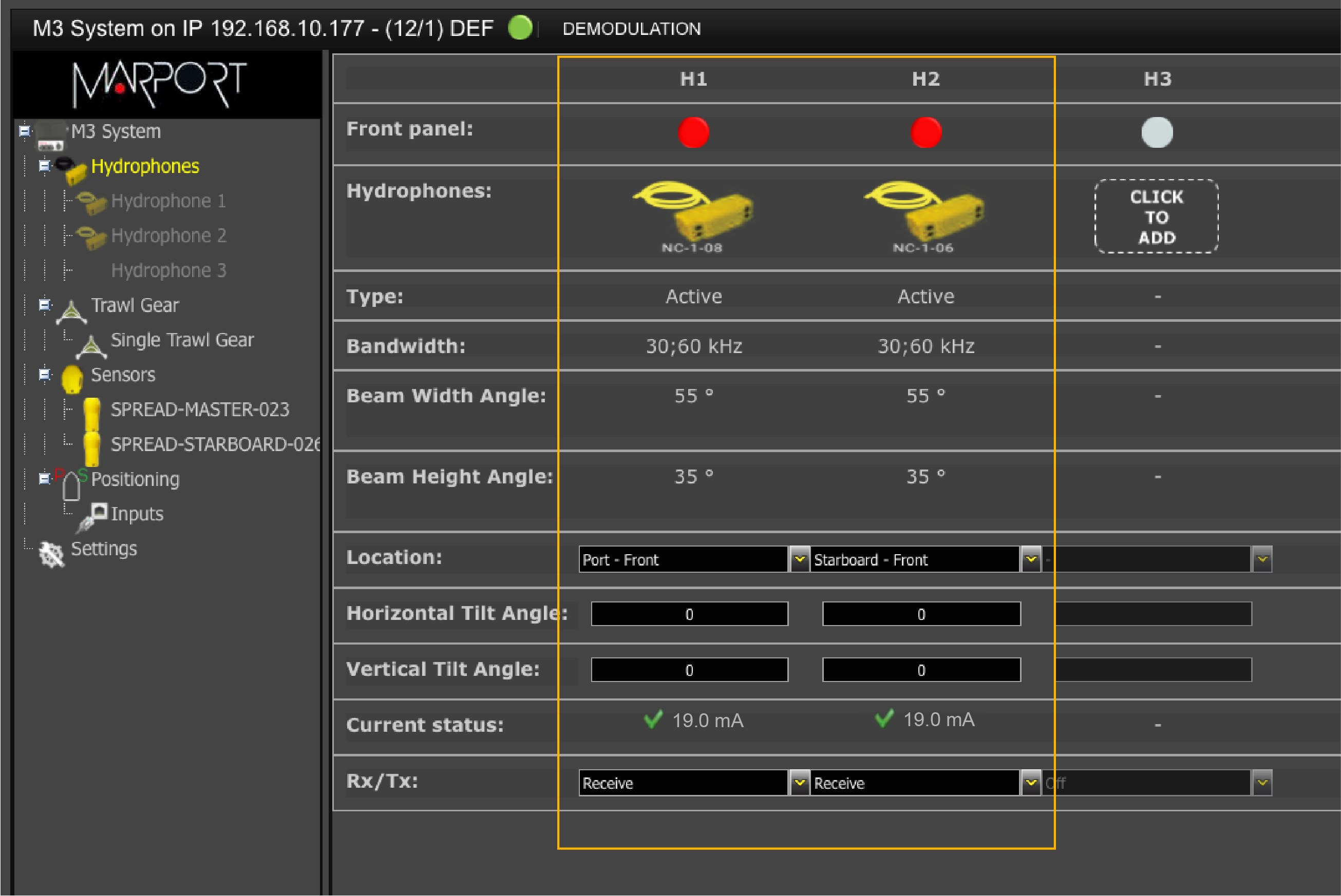
Figure 2. Hydrophone configuration for Slant Range sensors